

 SK
SK DE
DE IT
IT RU
RU CN
CN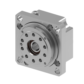

Series
The M series represents TwinSpin® high precision reduction gears of mini sizes. The M series is filled with grease for lifetime. The sealing of the M series reduction gears is secured by sealed (2RS) ball bearings, which are used as output bearings of the reduction gear, and also as the housing of the input shaft of the reduction gear (slight leakage of lubricant is allowed). Upon customer's request, SPINEA® is able to supply a completely sealed reduction gear. This design of the reduction gears allows the load to be mounted directly on the output flange or the case without the need for additional bearings.
Advantages
- small dimensions and compact design
- fully sealed by 2RS ball bearings
- simple installation
- zero-backlash reduction gear
- very low mass
- very high power density
- output deep groove ball output bearing with very low friction
- high performance of the reduction gear
- high precision
- high torsion rigidity
- high linearity of torsion chracteristics
- very low friction and high efficiency
TECHNICAL SPECIFICATIONS
TwinSpin M series mini reduction gear versions
|
Shape of the case |
b) The mounting part of the case is located on the input side of the TwinSpin high precision reduction gear |
|
Input shaft connection |
b) Indirect connection of shafts with rigid or flexible couplings c) Shafts are aligned according to the customer requirements
|
The M series high precision reduction gears are manufactured in several modifications according to the specification of the shaft and the case.
M series ordering specifications
|
Name |
Size |
Ratio | Series version |
Shaft version | ||
|---|---|---|---|---|---|---|
| P | H | S | ||||
|
TS
|
50 |
47, 63 | M | 6 | 8 | according to special request |
Note: An example of an ordering code of a modified TwinSpin reduction gear with a motor flange: TS 50 – 63 – M - P6– M235 – P231. The markings M235 and P231 for a specific modification are defined by the manufacturer.
Rating tables M series
|
Size |
Reduction ratio | Rated output torque |
Acceleration and braking torque |
Permissible torque at emergency stop |
Rated input speed | Rated output speed | Max. continuous input speed | Max. allowable input speed 1)6) | Tilting stiffness 1) | Torsional stiffness 1) |
| i | TR [Nm] | Tmax [Nm] | Tem [Nm] | nR [rpm] | nRout [rpm] | ncmax [rpm] | nmax [rpm] | Mt [Nm/arcmin] | kt [Nm/arcmin] | |
|
TS 50 |
47 63 |
18 | 36 | 90 | 2000 |
32 |
3000 | 5000 | 4 | 2,5 |
RIGHT TO CHANGE WITHOUT PRIOR NOTICE RESERVED
1/ Mean statistical value.
2/ Load at output speed nRout=nR/i. for TS 50 M it is 32 [rpm].
3/ Tilting moment Mc max at Fa=0. If Fa≠0 see par.3.5.1.
4/ Axial force Fa max for Fr=0, Mc=0. If Mc≠0 par.3.5.1.
5/ Radial force Fr max for Fa=0. If Fa≠0 see par.3.5.1.
6/ At 50% ncmax (max input speed in cycle)
7/ Applies to standard version of the high precision reduction gear with shaft connected by a key-way.
8/ a2 - is the distance of the radial force centre from the front of the output flange [m].
Rating tables M series
| Average no-load starting torque 1) | Average back driving torque 1) |
Max. lost motion |
Hysteresis | Max. peak tilting moment 2)3) | Max. radial force 2)4)8) | Max. axial force 2)5) | Input inertia 7) | Weight 7) |
| [cNm] | [Nm] | LM [arcmin] | H [arcmin] | M c max [Nm] | F rR [kN] | F a max [kN] | l [10-4 kgm2] | m [kg] |
|
4 3 |
3 2 |
<1,5 | <1,5 | 44 |
a2=0 1,44 a2>0 0,044/(a2+0,0305)
|
1,9 | 0,007 | 0,47 |
Note:
Load values in table are valid for nominal life Lh=6000 [Hrs].