

 SK
SK DE
DE IT
IT RU
RU CN
CN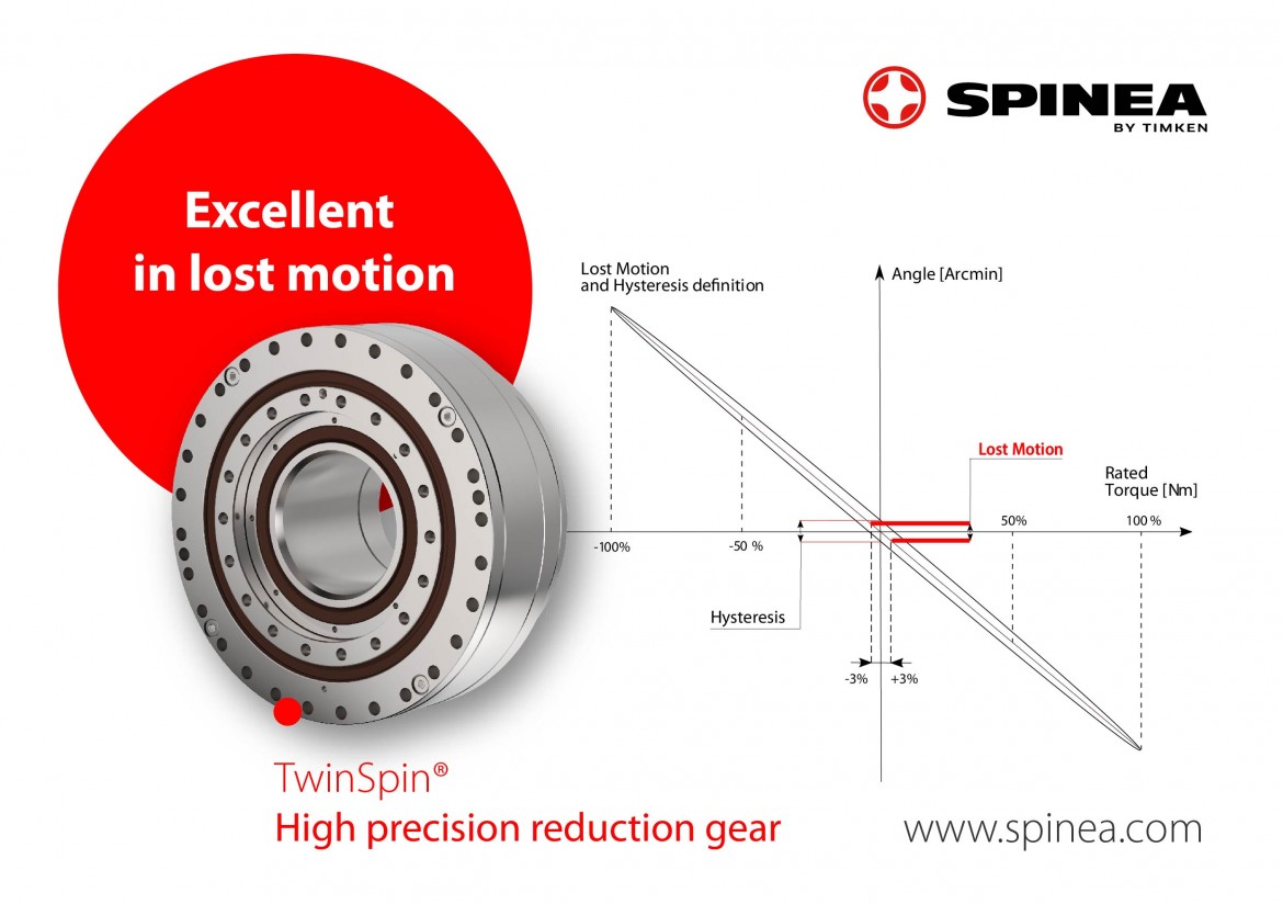
One of the most common questions about TwinSpin® reduction gears from SPINEA is how precise they are, or is there ever a question about the backlash in our reduction gears. With the increasing number of precision applications, especially in robotics, engineers and designers are familiar with lost motion. The aim of this article is to provide more detailed information about this parameter in TwinSpin® gears. Further on, we give short examples with different lost motion setups to show the differences between backlash and lost motion, and finally we mention something about the companion of lost motion - hysteresis.
Lost motion - how we define and measure it?
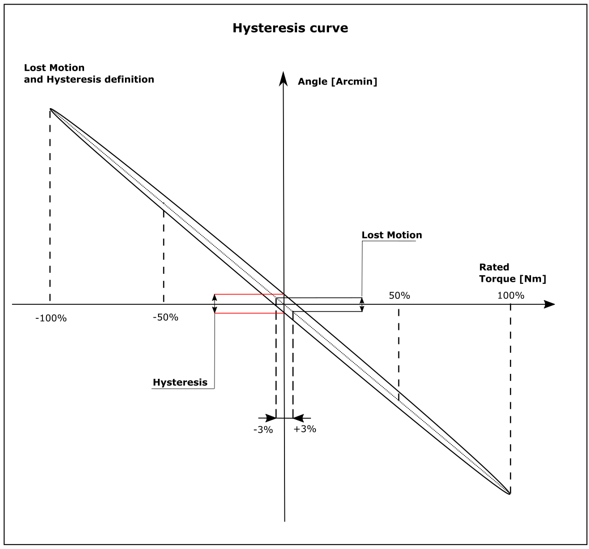
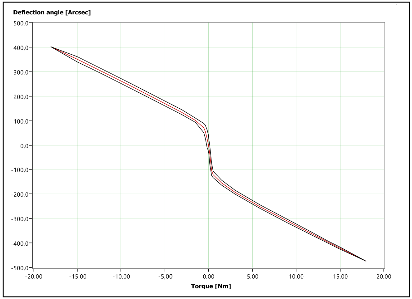
When you open our catalogue, you can find the following rather brief definition of motion loss. "If the input shaft and gear case are fixed and a torque is applied to the output flange, then the load diagram has the shape of a hysteresis curve. Loss motion is then defined as the pitch angle of the output flange at ±3% of the nominal torque measured on the centerline of the hysteresis curve." A schematic illustration is shown below.
In simplified terms, we can say that the lost motion is the sum of the material deformations, the mechanism stiffness and the internal clearances inside the gearbox that cause the motor motion to not produce the corresponding motion at the gearbox output during the direction-switching motion.
Picture 1 shows schematic drawing of the hysteresis curve which is plotted during loading test. Parameters such as hysteresis and torsional stiffness are also evaluated from this test. TwinSpin reduction gearbox is assembled in a standard way without backlash. The hysteresis, as can be seen in the figure, reflects the friction inside the gearbox. Hysteresis loss occurs as a result of friction of transmission components as well as friction in the output bearing.
Lost Motion or Backlash?
Many a times customer asks about backlash in our gears. The simple answer is that TwinSpin® reducers are backlash free but we have Lost Motion instead. How we should therefore relate backlash and Lost Motion?
In simple terms it can be said that every high precision mechanical transmissions /strain wave, cycloidal, planetary/ have lost motion but not all of them have backlash. We can therefore say that backlash is a part of Lost Motion. If there is a physical clearance between meshing components inside of the transmission it will show up in loading curve plot. Since transmission components are usually made from steel and have defined stiffness characteristics, we can say that under load this will cause "spring effect" which we call lost motion. So, to conclude the paragraph we may say that every gear which has backlash has also lost motion and the latter is of bigger magnitude when evaluated from loading curve plot.
Lost Motion settings in TwinSpin® gearboxes.
As indicated above, lost motion we have under control and it may be set to achieve desired value. For applications demanding high precision it can be set as low as 0,3 Arcmin, even in the smallest size G series reducers - TS75. With such a low setting is increased hysteresis as a consequence of higher internal friction. This can be also seen in lower efficiency and higher no-load starting and running torque.
The most common value for TwinSpin reduction gears is up to 1 Arcmin which is also precision reducers benchmark value.
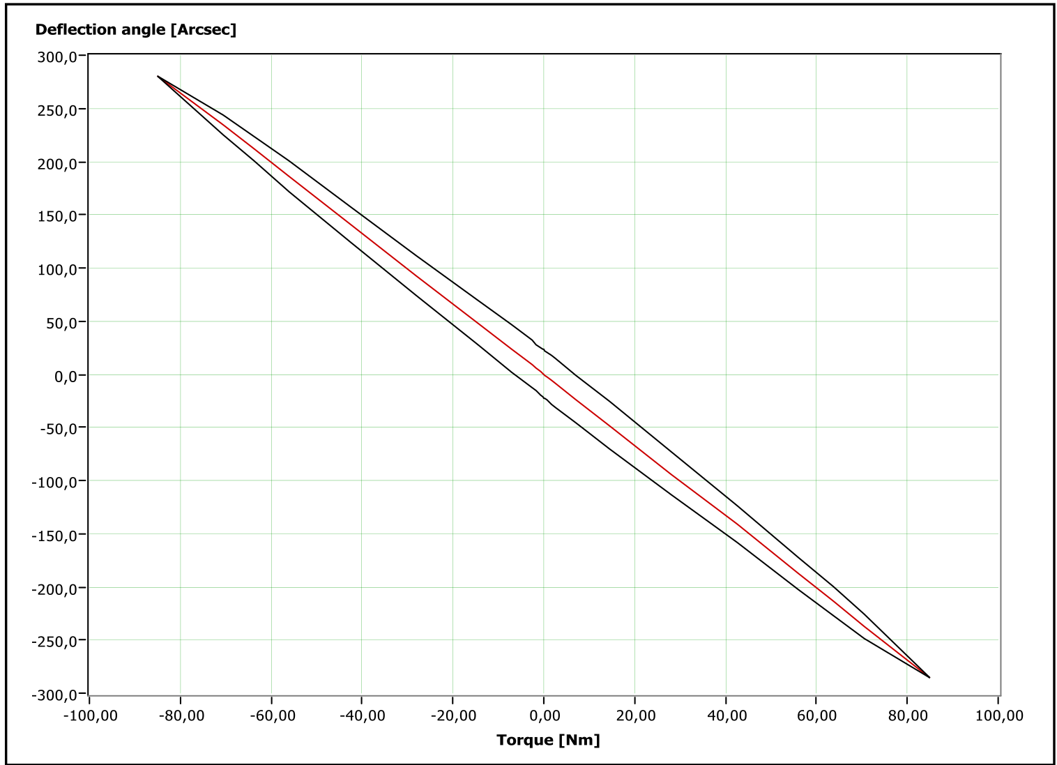
On the other hand, there are applications where the main requirement is not the precise movement of the output, but the transmission of power with the highest possible efficiency in the smallest possible size. In this case the lost motion can be set to much higher values around 3 - 4 Arcmin and we can say that we have introduced backlash since there is a clearance between internal components of a reducer. The real measurements of very low, standard and high lost motion (with visible clearance - backlash) are shown on the pictures below. All these measurements have been carried out on small gearboxes with an outer diameter of up to 100 mm.
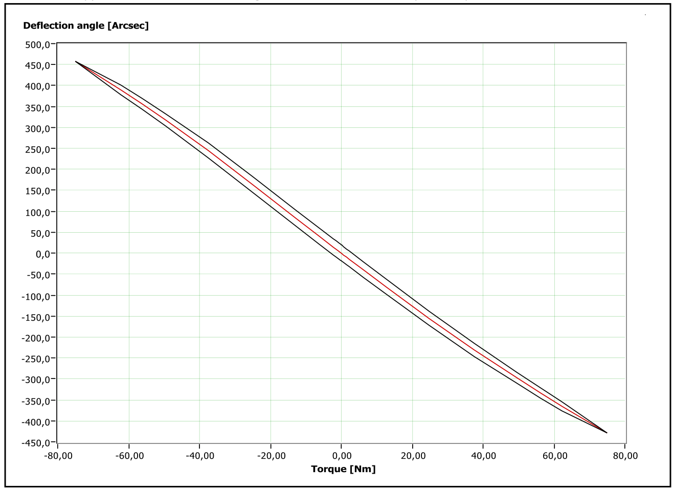
On the picture 4, there is visible internal clearance - backlash with typical S-curved load diagram typical for planetary gearboxes. These settings may be suitable for many applications where power transmission is only required. This is an example that TwinSpin gears may be set for various working conditions from the very beginning. All of the above measurements were performed on the new gearboxes.
The final point to mention about lost motion is that in order for application to be precise whole life, lost motion value at the beginning of service should be the same or very similar to the one at the end of product life.
About hysteresis.
When we talk about lost motion, we should also mention its sister parameter - hysteresis. Both of them are evaluated together from load diagram. As already mentioned, value of hysteresis indicate friction inside of the reducer and therefore also influences precision of the gear in applications where direction of rotation is changing. Simplified model on Picture 5 shows how it affects gear performance in precision positioning.
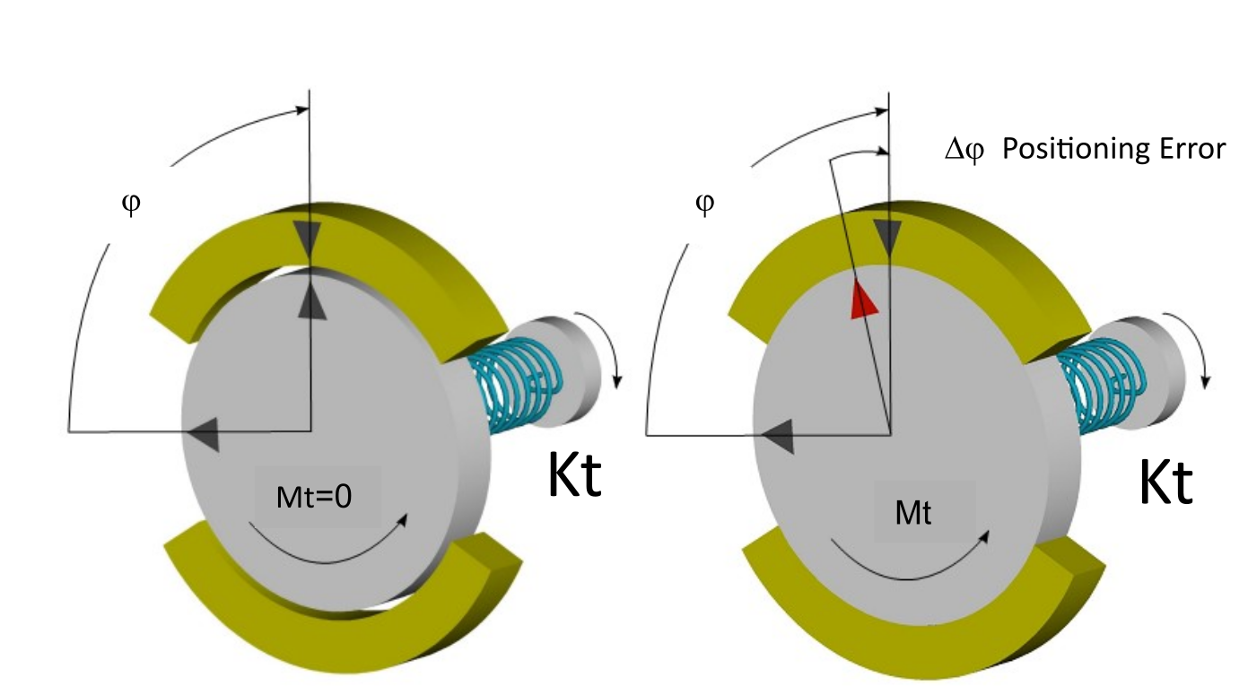
The simplified physical model above describes the correlation between torsional rigidity, internal friction and ability of the gear to achieve desired positioning precision. The disk represents object to be positioned with respect to brake. The disk is positioned with the spring, its torsional rigidity Kt represents torsional rigidity of reduction gear. Mc is total internal Coulomb friction of reduction gear reduced to the output. In the above model the Mc is represented by friction torque Mt generated by the friction between brake and the positioned member.
During precision positioning the task is to rotate disk by the angle ϕ from initial position by the means of torsional spring in a such way that disc is in exact opposite of the mark on the brake. If there is no touch of brake and disc, then no friction torque is generated and the task is easily done. However, as soon as we clinch disk with brake, friction torque Mt appears and then the task of precise positioning is becoming more difficult. The positioning error can be defined as Δϕ=Mt/Kt.
Angular hysteresis loss H of reduction gear then equals 2ϕ, that is H=2ϕ.
Final words.
When you open the SPINEA catalogue on the page with parameters of the reducers there is in lost motion column only one number. This means guaranteed standard value. But it doesn't mean that different setting is not possible. So, if your application requires something specific, let us know so we can tune the gearbox to deliver the right performance.


